Bill Chun Wai Hung
Q1)Find the values of
R1, C1, R2, C2 Using the version of spice that you want, you should be able to
describe the circuit and simulate it.
R1 = 8k ohm
C1 = 1u farad
R2 = 8k ohm
C2 = 1n farad
Low-Pass
f0 = 1/ (2*pi*R1C1) = 20Hz
High-Pass
f1 = 1/ (2*pi*R2C2) = 20kHz
Q2)Describe the circuit
using Spice.
with the source file
V_V1
IN 0 DC 0Vdc AC 1Vac
R_R2
0 OUT 1n
E_U4
N01107 0 VALUE {LIMIT(V(N00142,N01107)*1e13,-15V,+15V)}
R_R1
IN N00142
8k
C_C1 0 N00142 1u
C_C2
OUT N01107
8k
Q3)Set
an AC analysis to verify the cutoff frequencies
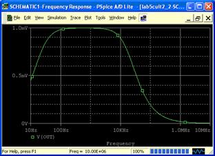
The AC Sweep shows a band-pass filter result with f0 = 20Hz and f1 =20kHz
The plot shows a shape of the bandpass filter result. In which the signal rises (20Hz) and drops later on (20kHz).
However, the Peak voltage in the plot is
only 1.0mV. The cutoff voltage should be close to 0.7V instead of 1mV.