Lab 2 Report ¨C DC and AC Analysis
with PSpice Software
Bill
Chun Wai Hung
A. Describe the Set-up
There are two parts of the lab.
In Part I, the operational
amplifier (op amp) is connected with only one voltage source. The connection is
like the diagram in figure 1, expect there has only one input. The input
resistance (R1) is 1k ohm, and the resistance across the op amp (R2) is 2k ohm.
The voltage gain is
Gain = Vout/ Vin = - 2k/1k = -2
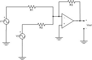
Figure 1.
In Part II, the set-up is shown in figure 1. R1 and R2 is set to
be 1k ohm, and R3 is 2k ohm. The output voltage (Vout) should be
Vout =
-(R3/R2)V2 ¨C (R3/R1)V1
The diagram for the op amp circuit is:
B. Desbribe Inputs
C. Describe What
you Observe
In part
I, the input voltage is 4V (the signal generator is 2V peek-to-peek), so the
expected output voltage (Vout) is 4V x 2 = 8V. The oscilloscope showed a
peek-to-peek voltage of 8.109V, which is the experimental output voltage. The
result is close to the expected output voltage (8V). The percentage difference
is 1.36%.
Vin =4V,
Gain = 2, Vout =8V
In part
II, the first dc input voltage (V1) is 0.309V, and the second ac input voltage
(V2) is 2V(the signal generator shows 1V), so because
Vout =
-(R3/R2)V2 ¨C (R3/R1)V1
Where R1=1k, R2=1k, R3=2k
Therefore, the voltage out is expected to be around 2V x 2 = 4V. The oscilloscope showed a
peek-to-peek voltage of 4.188V, which is the experimental output voltage. The
result is close to the expected output voltage (4V). The percentage difference
is 4.70%.
The
first dc input voltage(V1) is set to be small, because V1 only gives an offset
of the output voltage. When V1 is increased (say from 0.2V to 0.6V), the output
voltage is wave form shifted upper. In similar case, when V1 is decreased (say
from 0.6V to 0.2V), the output voltage wave form is shifted lower. This is
because V1 is a dc input, and the dc input does not change the ac waveform, and
the dc input only shift the output waveform upper or lower. In additional, when
the waveform is shifted too high or too low, the waveform becomes a flat line.
This is because the supply voltage of the op amp is not large enough to
generate an output voltage that the input voltages (V1 and V2) generated. In
other words, the supply voltage is not large enough to generate the required
waveform.
D. What you can deduce
In this
lab, an audio mixer is desired. The circuit should sum two inputs together. In
the lab, it does show the input added together, because the dc voltage shifts
the ac waveform generated in the oscilloscope (output).
What I
am planning to do in order to claim my circuit works.
I am
going to change my input voltage to other voltages. Like 2 V and 2V, and the
supply voltage to higher voltages, like 12V. In this case, my circuit should
add the voltages together. Because the gain is 2, so the output voltage should
be 2V x 2 + 2V x 2 = 8V.