Peter Lau
Bill Chun Wai Hung
Lab 14 Report – Propagation Delay
and Inverter Ring Oscillator
A. Describe the Set-up
The Circuit
1 setup is shown in figure 1.
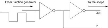
Figure 1
The
Circuit 2 setup is shown in figure 2.
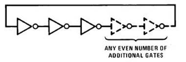
Figure 2
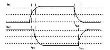
Figure 3 – measure the time of the 10% and 90% points
B1. Describe Inputs
Stimuli:
DC 5V to
drive the inverters
Inverters
Chip: 74LS04
AC 5V
square wave
C. Describe What you Observe
Circuit 1.
Detla t (2 inverters) = 15.40ns
Detla t (1 inverters) = 7.70ns
Rise Time = 9.80 ns
Fall Time = 7.80 ns
Circuit 2.
Oscillation
Frequency = 24.91MHz
The propagation delay is (1/24.91MHz) / 6 =
6.69 ns
D. What you can deduce
For
Circuit 1, the experimental propagation delay (7.70ns) agrees with the
propagation delay stated in the data sheet (from 3ns to 10 ns).
The rise
time measured between the 10% and 90% points of the input and output signal is
9.80ns. The fall time measured between the 10% and 90% points of the input and
output signal is 7.80ns.
From
Circuit 2,
The
three inverters oscillate when connected in series. The oscillation frequency
is 24.91MHz.
The
propagation delay is (1/24.91MHz) / 6 = 6.69 ns
Divide
the time by 6 because there are 3 inverters and rise and fall delay(2 delay).
Q1) Explain why the ring circuit generates oscillation.
Because the logic opposite is feedback to the input after certain time
delay. This
causes the first gate to flip and the reverse gate is propagated to the
remainder of the chain, and this process repeats itself during the process of
oscillation.
Q2) Is
the propagation delay the same for the two experiment?
Yes,
they are the same. The propagation delay for circuit 1 is 7.70ns and that of
circuit 2 is 6.69ns, very close to be the same.
Q3) If
not, explain what could be the possible causes.
The wire
connections of the circuit can cause extra delays.