Peter Lau
Bill Chun Wai Hung
Lab 12 Report
– NMOS Common Source Amplifier
A. Describe the Set-up
The Circuit
setup is shown in figure 1.

Figure 1
B1. Describe Inputs – Ideal Case
Stimuli:
vi:
Sinusoidal
Amplitude
100mv
K = 0.82
VT = 2.9
V
Vdd =
10 V
Av = 20
MOSFET =
NMOS = Model BS170
C1 = C2
= 10uF.
Av= gm(Rd)
Av = 2K(Vgs – Vto)(Rd)
…(1)
Id(Rd)
= 5V
K(Vgs – Vto)^2 (Rd) = 5V … (2)
Solving
(1) and (2)
Av = 2K(Vgs – Vto)(Rd)
… (1)
20 =
2(0.82)(Vgs – 2.9) (Rd) …
(3)
K(Vgs – Vto)^2 (Rd) = 5V … (2)
(0.82)(Vgs – 2.9)^2(Rd) = 5V …(4)
Solving
(3) and (4)
Vgs =
3.40V
Rd =
24.4 ohm
Substitue Vgs = 3.40V
Id = K(Vgs – Vto)^2*
…(5)
Id =
(0.82)(3.4 – 2.9)^2
Id =
205mA.
Vds = Vdd – V(Rd) = 10V – 0.205 x 24.4
Vds =
5.0V
In other
words, the Ideal Results are
Id=205mA.
Rd =
24.4 ohm
Vds
=5.0V
Av =
20.1
B2. Describe Inputs – Experimental Case
The
setup of the Experimental Case is the same as that of the Ideal case, expect
R1=6.9k
R2=3.3k
Rd = 36
The
experimental circuit setup is shown in Figure 2.
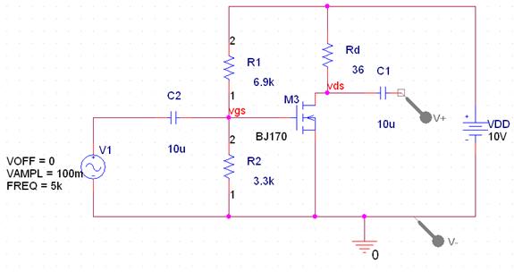
Figure 2
Therefore
Vgs=Vdd(R2/(R1+R2))
Vgs=10V(3.3k/(6.9k+3.3k))
Vgs =
3.24V
From (3)
20 =
2(0.82)(Vgs – 2.9) (Rd)
(20/(2*0.82)) = (Vgs – 2.9) (Rd)
12.2=
(3.24 – 2.9) (Rd)
Rd =
35.9 ohm, for which, a 36 ohm resistor is used.
From (5)
Id = K(Vgs – Vto)^2
…(5)
Id =
(0.82)(3.24 – 2.9)^2
Id=94.8mA
V(Rd)
= Id x Rd = 0.0948 x 36 = 3.40V, which is not the ideal 5V.
So Vds = Vdd-V(Rd)
= 10V – 3.4V = 6.6V,
for V(Rd) is the voltage across
Rd
In other
words, the Expected Experimental Results are
Id=94.8mA
Rd = 36
ohm
Vds
=6.6V
Av = 20
C. Describe What you Observe
The
experimental Vo =Vds = 4.384V.
The
input (Vin) amplitude is
100mA, which is 200mA peak to peak
Amplification
(Av) = Vo/Vi = 22
The
measured Id is
5.616/36ohm
= 0.156A
In other
words, the Actual Experimental Results are
Id=156 mA
Rd = 36
ohm
Vds =4.384V
Av = 22
D. What you can deduce
The
Percentage Difference of the Amplification
=|Target
Value – Experimental Value|/Target Value x 100%
=|20 –
22|/20 x 100%
=10%
The
Percentage Difference of the Id
=|Target
Value – Experimental Value|/Target Value x 100%
=|94.8mA
–156mA|/94.8mA x 100%
=64.6%
The
Percentage Difference of the Vds
=|Target
Value – Experimental Value|/Target Value x 100%
=|6.6V –4.384V|/6.6V
x 100%
=33.6%
The Experimental
values are off from the calculated value by the percentages shown above. The
error maybe caused by the non-perfect transistor or non-perfect resistors.
Q1) Qualitatively,
describe what happens if Rd increase.
If Rd
Increase, then Vds decreases.
Because Vds decreases, so Vo
decrease, and the amplification decreases.
Q2)Qualitatively,
describe what happens if R2 decreases.
If R2
decrease, then Id decreases. Since Id decreases, V(Rd)
decreases, and Vds increases, so the Vo is increased,
so the amplification increased.