Lab 6 Report
иC Active Filter
Bill
Chun Wai Hung
A. Describe the Set-up
The
setup is shown in figure 1.

Figure 1
With a
source file of
E_U3 N10100 0 VALUE {LIMIT(V(N09945,0)*1E6,-15V,+15V)}
V_Vi1
N09989 0 DC 0Vdc AC 1Vac
C_C1
N09945 N09877
1u
R_R1
N09989 N09877
4.3k
C_C2
N10100 N09945
1n
R_R2
N10100 N09945
8.25k
B. Desbribe Inputs
R1 =
4.3k ohm
C1 =1u
farad
f1 =
37Hz, almost 40Hz
R2 =
8.25k ohm
C2 = 1n
farad
f2 = 19.3kHz , almost 20kHz
The Op
Amp used is LMC64, the kind of op amp that is used in the previous labs.
Stimuli:
The Voltage is 1V in amplitude, and the value equals to 2 V peak-to-peak voltage.
With a
stimulation of pSpice, the ideal result should be
close to the one shown in Figure 2.
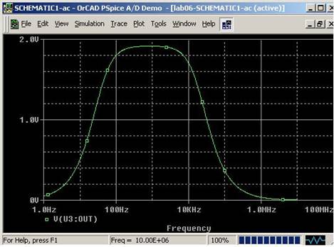
Figure 2
C. Describe What you Observe
The
circuit generated an experimental voltage values shown in Table 1 and Figure 3.
Table 1.
|
Frequency
(Hz) |
Voltage
(mV) |
|
10 |
31 |
|
15 |
34 |
|
20 |
41 |
|
30 |
47 |
|
40 |
62 |
|
50 |
72 |
|
60 |
78 |
|
70 |
78 |
|
80 |
78 |
|
90 |
78 |
|
100 |
94 |
|
200 |
125 |
|
300 |
190 |
|
400 |
281 |
|
500 |
285 |
|
600 |
375 |
|
700 |
453 |
|
800 |
469 |
|
900 |
578 |
|
1000 |
656 |
|
2000 |
1156 |
|
3000 |
1582 |
|
4000 |
1766 |
|
5000 |
1844 |
|
6000 |
1812 |
|
7000 |
1781 |
|
8000 |
1734 |
|
9000 |
1703 |
|
10000 |
1656 |
|
20000 |
1125 |
|
30000 |
781 |
|
40000 |
593 |
|
50000 |
437 |
|
60000 |
375 |
|
70000 |
328 |
|
80000 |
250 |
|
90000 |
234 |
|
100000 |
172 |
|
200000 |
156 |
|
300000 |
125 |
|
400000 |
175 |
|
500000 |
144 |
|
600000 |
156 |
|
700000 |
203 |
|
800000 |
203 |
|
900000 |
150 |
|
1000000 |
312 |
Figure 3
D. What you can deduce
The
result of the experiment is that. The Experimental Plot of the voltage value
resembles the ideal voltage values shown in Figure 2. The peak voltages are
both around 1.9V.
What I am
planning to do in order to claim my circuit works:
If the
input voltage is changed from 1V to 2V, the output voltage would change
accordingly. However, the cutoff frequencies will not be change. In other
words, the shape of the voltage against frequency plot will still be the same
except the whole graph is scaled upward.
The
cutoff frequencies (37Hz and 19.3kHz) is not as
obvious in the experimental plot. In other words, the voltage change around the
cutoff frequencies (37Hz and 19.3kHz) are not as rapid
as shown in the ideal plot. This is because the resistors used during the lab
are not ideal. A small difference of the resistance from the ideal value
changes the frequency response a lot. This is why the voltage rise and drop
around the cutoff frequencies are not as rapid as the ideal plot.
This
experiment shows the differences between ideal case and the real case. Besides,
the purpose of this experiment is to be exposed to active filters. An active
filter is incorporating passive filters with op amp. Active filters can change
the gain of the op amp to make the output voltage higher when the frequency is
in the allowed range (by changing the values of R1 and R2). The gain of the
Op-Amp is иCR2/R1. On the other hand, a passive filter is not capable of changing
the gain of the output.
Further
more, an active filter consist of an op amp, which separate the high-pass and
low-pass filter. On the other hand a passive filter is not capable of
separating the high-pass and low-pass filter. In other words, the high-pass and
low-pass filter in the passive filter would influence each other.
Q3) In
the series connection of low pass filter and high pass filter, do the cutoff
frequencies change form the original computed f1 and f2?
Yes.
Q4) And if they change, what, do you think, is the reason?
The
reason for the change is that originally when the two filters are separated,
the filters have separate circuit and separate current. The filters are
mutually exclusive in this case. Therefore the filters donбпt influence each
other.
However,
when the low pass filter and the high pass filter is connected in series. The
filters affect each other. When the two filters are connected in series, the
filters share the same current, that is the current
from the output of the first filter will flow into the input of the second
filter. In this case, the filters affect each other, and this cases the cutoff
frequencies to be off from f1 and f2.
The
solution to prevent the low pass filter and the high pass filter affecting each
other is to put an op amp between the low pass filter and the high pass filter.